Plant Schematic
Draw an interactive floor plan of your plant, with multiple flow types and tabs for different floors or views.
What this is for
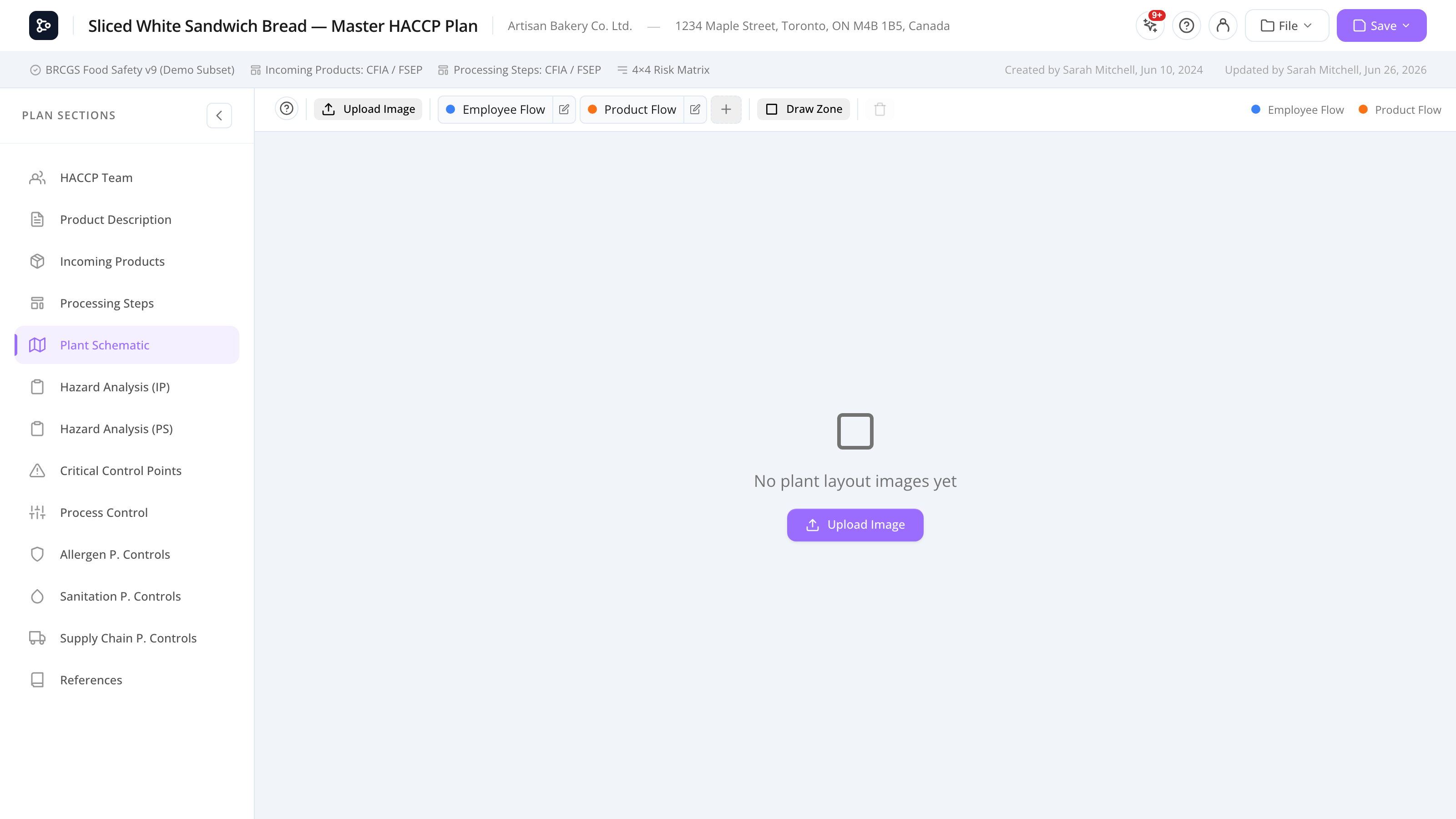
The Plant Schematic section is a visual canvas for sketching the floor plan of your plant. You can draw walls, rooms, and equipment, and overlay one or more polyline flows that show how product, personnel, waste, or other items move through the space. Each flow type has its own colour, line style (solid, dashed, dotted, and more), and thickness, so different flows stay visually distinct even in black-and-white print.
You can also mark cross-contamination zones — named, coloured rectangles over sensitive areas (e.g., a raw-to-cooked transition) with rich-text notes explaining the risk and its controls.
Multiple tabs let you keep separate views — typically one per floor, or one per perspective (e.g., raw material flow, finished product flow, sanitation flow).
The schematic is included in the printed plan with a print-optimized version that preserves colours, labels, and zones (each zone’s notes are listed beneath the diagram).
Common tasks
How to add a tab (a new floor or view)
- Click the + at the right of the tab bar.
- Type a name (e.g., Ground floor, Upper floor, Sanitation flow).
- The new tab opens with an empty canvas.
How to draw walls and rooms
- In the toolbar, pick the rectangle or polyline tool.
- Click and drag (or click point-by-point) to draw.
- Repeat for each wall or room.
Each shape has a fill colour, stroke colour, and stroke width that you can change after drawing.
How to add a polyline flow
Polylines represent how something moves through the plant — raw material, finished product, personnel, waste, etc.
- Click + Add flow in the toolbar.
- Pick a flow type from the popover (or create a new one).
- The cursor switches to drawing mode.
- Click points along the path you want to draw. Each click adds a vertex.
- Press Enter or Esc to finish.
The polyline appears in the chosen flow type’s colour and line style.
How to reshape a line after drawing it
- With the Select tool, click the line. Its bend points and endpoints appear as draggable handles.
- Drag any handle to move that vertex — the rest of the line follows.
- Handles are clamped to the image bounds, so a vertex can’t escape the floor plan.
How to change a line’s endpoint markers
Each line can carry its own marker on each end — none, an arrow, or a diamond.
- Select the line.
- A Start / End marker picker appears.
- Pick the marker for each end independently.
Put an arrow on both ends to show a bidirectional flow. Existing lines keep their familiar single end-arrow until you change them.
How to manage flow types
Click the flow type button in the toolbar (or the gear icon next to a flow). The popover lets you:
- Rename a flow type.
- Change its colour.
- Change its line style — solid, dashed, dotted, dash-dot, long-dash, or dash-dot-dot.
- Change its thickness — thin, normal, or thick.
- Add a new flow type.
- Delete a flow type (existing polylines using it become uncategorized).
Style changes apply to every line of that flow type, on canvas and in print — a big help for keeping flows tellable apart on a black-and-white printout.
How to mark a cross-contamination zone
- In the toolbar, pick the Draw Zone tool.
- Drag a rectangle over the area of concern. The zone editor opens right away.
- Give the zone a name, pick a colour, and write notes in the rich-text editor (what the risk is, how it’s controlled).
- Save. The zone appears as a translucent coloured rectangle with its name.
To edit later, double-click the zone. To move or resize it, select it and drag the body or corner handles. Zones print with the schematic — the diagram shows the coloured rectangles, and each zone’s name and notes are listed in a table beneath it.
How to switch between tabs
Click any tab name in the tab bar at the top of the schematic. The canvas switches to that view. Each tab keeps its own shapes and polylines.
How to delete a tab
Hover the tab and click the × that appears, then confirm. Everything on that tab is removed permanently.
How to export or print the schematic
The schematic is included automatically in the Print preview. For a standalone export (e.g., to share with an architect), use File → Export image while on the schematic section to download a PNG of the current tab.
Screen reference
Tab bar
| Element | What it does |
|---|---|
| Tab name | Click to switch. Double-click to rename. |
| + | Add a new tab. |
| × on hover | Delete the tab. |
Toolbar
| Tool | What it does |
|---|---|
| Select | Click a shape or polyline to select; drag handles to resize/move. |
| Rectangle | Draw a rectangle by click-drag. |
| Polyline (closed) | Draw a closed shape with click-by-click vertices. |
| + Add flow | Draw a polyline flow with a chosen flow type. |
| Draw Zone | Drag a rectangle to mark a cross-contamination zone (name, colour, notes). |
| Flow types | Manage flow type names, colours, line styles, and thickness. |
| Stroke / fill colour | Change the selected shape’s appearance. |
| Stroke width | Change line thickness. |
| Undo / Redo | Step backwards/forwards through changes. |
| Delete | Remove the selected shape. |
Canvas
Pan with Space + drag, zoom with the mouse wheel.
FAQs
Can I import a CAD/DXF file as the floor plan? Not directly. Workarounds: import a JPG/PNG of your floor plan as a background image (drag it onto the canvas), then trace over it using the rectangle and polyline tools. Hide the image before printing if needed.
The flow lines are messy — can I make them look cleaner? Use shorter, more deliberate clicks while drawing. After drawing, select a line and drag its vertex handles to align with rooms. You can also change each flow type’s line style and thickness.
How do I show a flow that goes both ways? Select the line and set an arrow marker on both the start and the end — a two-headed line reads as bidirectional. You can also mix markers (e.g., diamond at the source, arrow at the destination).
Will my schematic still be readable in black-and-white print? Yes, if you give each flow type a different line style (solid vs. dashed vs. dotted…) rather than relying on colour alone. The styles carry through to print and PDF exactly as on canvas.
What’s the difference between a polyline shape and a polyline flow? A shape has fill and stroke and represents physical objects (a wall, a tank). A flow is a directional polyline tied to a flow type — it represents movement and is typically open-ended with arrowheads.
My schematic looks fine on screen but small in print. Use File → Print preview and check the schematic page. The renderer fits the tab to a single landscape page by default. If your floor plan is very long, consider splitting it into two tabs.
Can I have animated flow arrows? Not currently. Arrows are static, but you can use coloured flow types and labels to make different flows easy to distinguish.
Are tab names included in the print? Yes — each tab is its own page in the printed schematic, with the tab name as the page title.